3D touch V3.0 Install instructions
3D touch V3.0 Install instructions
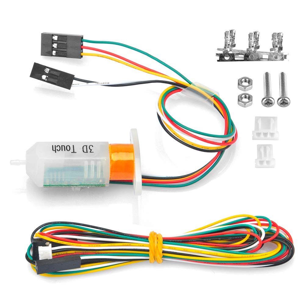
3D touch is a reliable lower cost alternative to Bltouch.
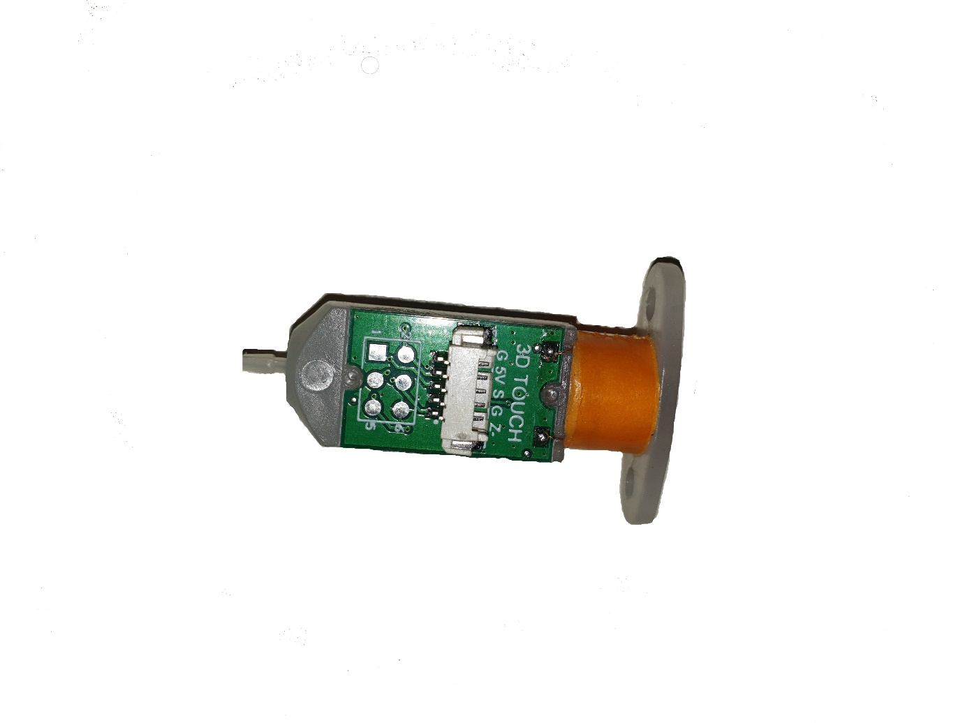
The first thing you’ll notice is the wiring colours are different to bltouch, other versions and brands of 3D touch. You can usually find the pinout marked on the printed circuit board of your 3d touch, you may need to remove the plug to see it. Once you can see the pin designation you can compare this to the colour codes on your cable.
The 3D Touch we use have the following designations,
Servo wires; Red 5V, Green Ground, Yellow signal
Endstop wires; Black Ground, White Signal
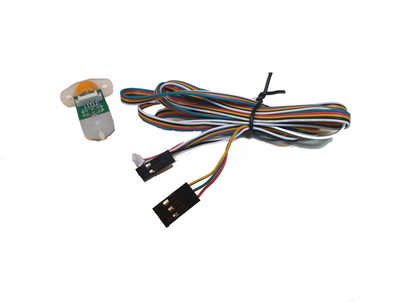
The 3D touch as shown below is setup from the factory to suit boards like SKR Mini, SKR 1.4, MKS Gen 1.4 and Creality. But you should always double check the pinouts as provided by the maker of your board.
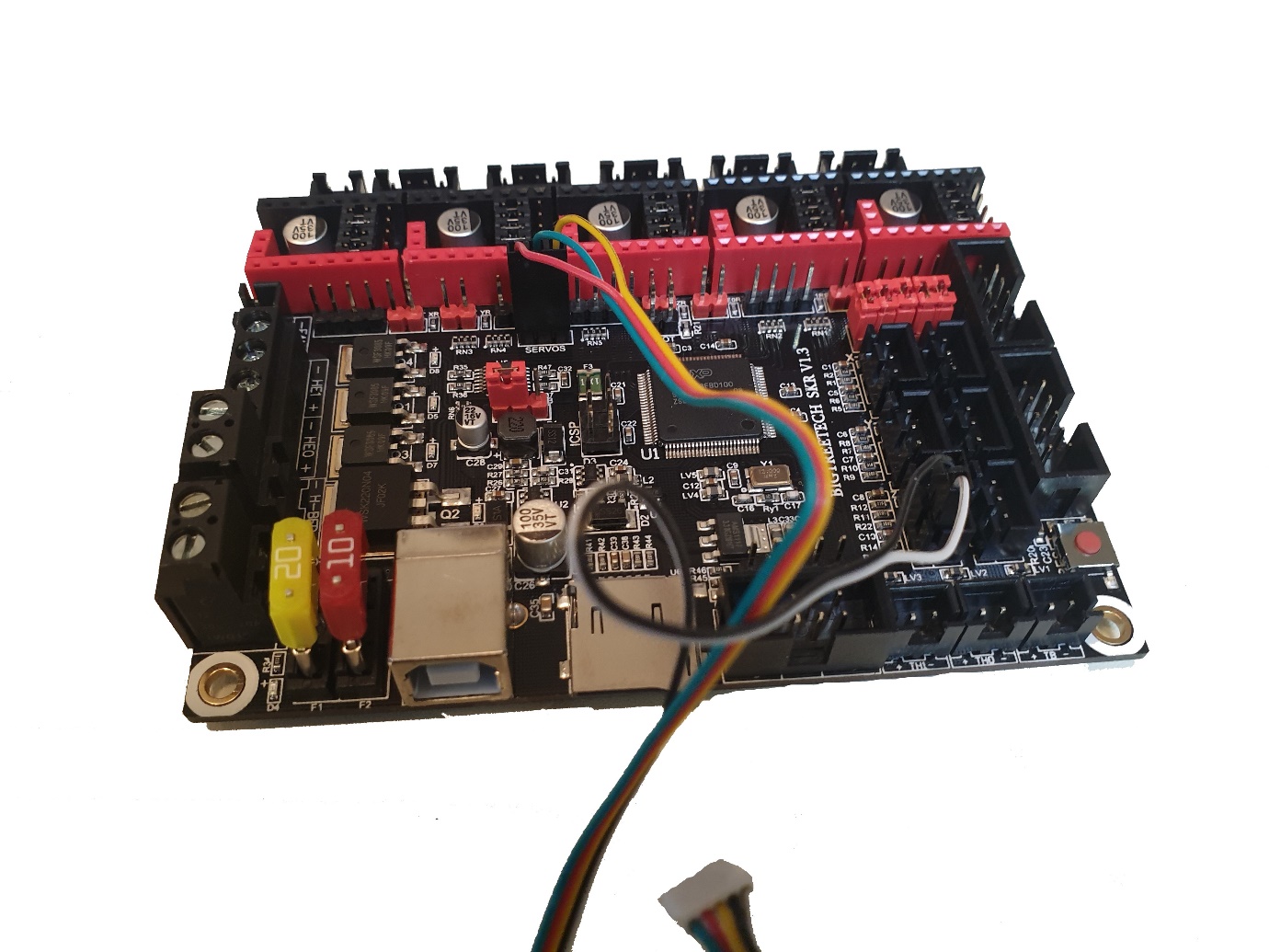
To connect the 3D Touch to a board like SKR 1.3 you’ll need to change wiring order on the 3 pin connector. This is fairly easy, just gently lift the tabs on the black connector body (don’t bend the tabs too far back or they’ll break) and remove each wire. Make sure the tabs are pushed back down on the connector body and reinsert the wires as below.
The SKR 1.3 has the pins changed around compared to many other boards
Marlin Firmware Changes
As you’re Googling around you might find posts telling you to set ENDSTOP_INVERTING to true, this is incorrect, the setting must be false to make this probe work. If you get this setting wrong the printer will attempt to probe but the nozzle will hit the bed and the endstop will never trigger.
We’re going to run through the setup for Marlin 2.0, open configuration.h in your editor of choice and scroll down to around line 630 and check that ENDSTOP_PULLUPS are defined and that ENDSTOP_PULLDOWNS are disabled.
As mentioned above at around line 650 check that BOTH ENDSTOP_IINVERTING for ZMIN and ZMIN_PROBE are set to false.
At around line 835 check that Z_MIN_PROBE_USES_Z_MIN_ENDSTOP_PIN is defined.
Around line 890 check that DEFINE_FIX_MOUNTED_PROBE is commented out, especially if you’ve already been using another type of probe such as a P.I.N.D.A.
Around line 909 make sure define BLTOUCH is enabled
Around line 995 you’ll find define NOZZLE_TO_PROBE_OFFSET, take the time to measure these distances accurately. If the probe pin is to the right of your nozzle the value is entered as a positive such as 10, to left is entered as a negative such as -10. If the probe pin is behind your nozzle it’s a positive and in front is a negative. The third value on this line is Z offset, leave this as zero for now and adjust it in you printer’s config menu later.
Around line 1000 you’ll find define PROBING_MARGIN, you can leave this at zero but we prefer a bit of margin and set it to 10.
Around 1157 you’ll find define MIN_SOFTWARE_ENDSTOP_Z you can either disable all software min endstops or just comment out this line. This allows you to adjust a negative z offset which you will need for the 3D Touch probe.
Around line 1240 you’ll find mesh bed levelling, we use bilinear levelling. We’ve tried ABL but found it buggy. To use bilinear make sure define AUTO_BED_LEVELING_BILINEAR is uncommented.
Around line 1290 you’ll find define GRID_MAX_POINTS_X we like to set this to 4 which gives 4 rows of 4 probes, but you can set this lower. Be careful setting it higher as some 8 bit boards don’t have enough memory to store a large grid.
That’s it for configuration.h and these settings should have your 3D Touch working. Save the file and close.
There’s more settings in configuration_adv.h that we like to change.
Open configuration_adv.h and scroll to around line 660 you’ll find define BLTOUCH_DELAY the default value is 500, if you find your probe is ultra-reliable you can reduce this to a lower number like 300 or 200 or even comment it out altogether. Also around 669 you’ll find define BLTOUCH_FORCE_SW_MODE this can be useful if you are getting false triggering from your probe.
Around line 687 you’ll find define BLTOUCH_SET_5V_MODE, enable this if your probe is one of the newer ones and your supplier confirms it can run at 5 volts.
That’s it, run your firmware build and upload to your printer.
The probe should run a self-test at bootup and rest with a blue and red led lit.
If you have no lights, the three pin connector is wired incorrectly or plugged into the wrong port, double check your wiring and the correct pinout for your board.
If it faults and sits with a red led only, turn your printer off and check the 3D Touch pin, it should move freely, plus as you slowly push it up it should snap to the retracted position. If the pin is sticky unmount the probe and remove the top grub screw, take care NOT TO BEND THE PIN. You can then gently push it up with something small until you can grab and remove it. Carefully check the pin for any stray flashes of plastic. If you find any or even if a spot feels rough, gently remove the flash or rough section with a sharp blade. Go easy you only want to lightly scrape it until if feels smooth. Also check the pin is straight. You can gently straighten the pin if it’s bent, again go slowly and make gentle changes. You’ll have it right when the pin moves freely and it snaps up into place (with the grub screw reinstalled). Resist the temptation to prise the PCB off your probe, there’s nothing under there you can service.
If you issue a homing command and the probe continuously deploys and stows the probe (your printer may also display “Stopped”) then the probe is not sending the endstop pulse to the printer. You may have your white and black wires the wrong way around or you may have plugged into the wrong endstop socket, so double check your wiring.
Enjoy your new probe!