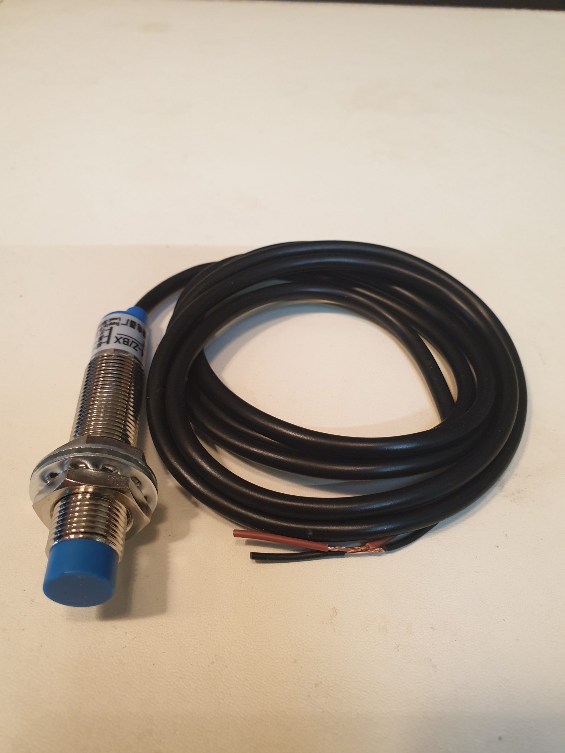
Wiring an Inductive Probe Sensor
Wiring diagram for NPN Inductive probe running 6-36 Volts
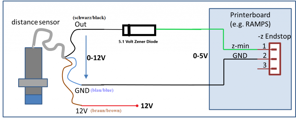
No doubt you’ve seen posts using resistors with these probes, we found it makes your probe unreliable, we prefer the 5.1 volt Zener diode method as shown above.
**Important** play close attention to the colour codes, these probes use international colour designations.
The signal wire from the probe is black and goes to the green end stop connector via the Zener diode, this limits the output of the probe to 5.1 volts. Pay close attention to the orientation of the Zener – yes the band on the Zener points TO THE PROBE.
The blue wire from the probe is ground and goes to the black ground end stop wire.
You might be thinking why not pick up voltage from end stop pin 3? – because it’s only 5 volts and these probes need at least 6 volts and work best at 12 – 24 volts. Connect the brown wire from your probe to the +volt supply of your printer, usually from an auxiliary connector. You can pick up 12/24 volts directly from your power supply output if you prefer, but double check the voltage first.